
| Main technical specification Electronics of the device Results obtained on Solver-P47 |
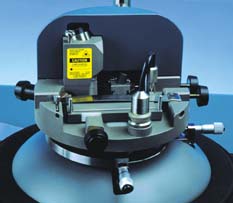
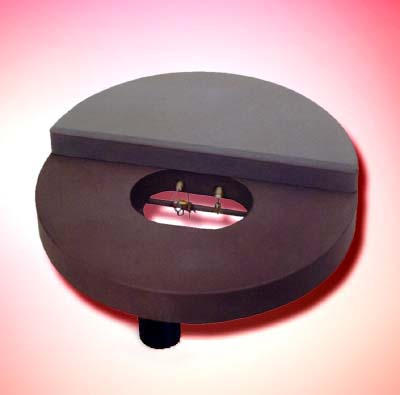
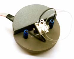
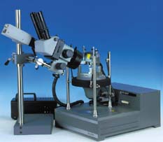 (a) - general view | 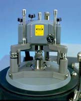 (b) - head with the sample holder |
|
The cantilever deviation is registered by a 100 % stable optical system. During the scanning by cantilever a special cantilever tracking system takes care that the laser beam is continuously positioned to the top of the cantilever tip while scanning. The problem to be solved is that when the cantilever scans in free space (i.e. not in interaction with any surface) the reflected ray from the cantilever tip should hit the centre of the four-segment photo diode without the slightest deflection. The solution of this problem is realised by a simple though brilliant mirror system that is fixed to the scanner. The solution provides absolute deflection stability as if the cantilever was not scanning. Four micrometric adjustment screws fast and easy do the initial adjustment of a recording system. A stepper motor carries out the system rough approach with 200 steps on 360°. Each step is divided in 64 sub-steps, that ensures a minimum single shift of about 25 nm, that it is much less than the Z range of the smallest scanner (not less then 1.5um). The design of the spot locating system is carried out such, that the return to the spot of the previous scan is carried out with a precision of less then 0.1um. Even if one makes many toward-back cycles. This is equally valid for operation in liquids. It facilitates the possibility of long-term multi-day experiments. Thus allowing one to study processes of corrosion, ageing, habitability of cells etc. etc…. Below there are AFM images of a diffraction grating after first (a) and 10 cycle's (b) approaching operations sample-cantilever, and on (c) there is a difference of these images. The sample was assigned for each cycle on a fixed distance 1 mm. From a comparison it is visible, that the relative displacement of images is in a limit of 0.1um, that confirms the high quality of approaching guaranteeing the possibility of long observations of an object. |
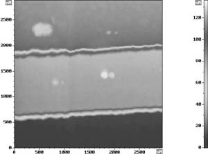 a | 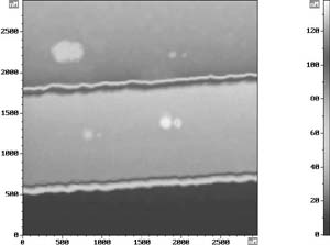 b |
|
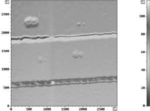 c |  d |
|
All operations of the device are completely software controlled. The software runs on any modern IBM compatible PC. The universal High-Q electronic block, that is used throughout the whole range of NT-MDT's Scanning Probe Microscopes, supports a large range of virtual all modes available in today's SPM technology. The electronics and software of the device allow working in the following modes:
The device enables imaging in STM and AFM mode simultaneously during one single scan. All these modes are realised by a single SPM Solver-P47 equipped with any of two heads: |
 The head for scanning by sample | The head for scanning by cantilever |
| For the specific Scanning Tunnelling Microscopy and Spectroscopy any of the following two heads are applied: |
 (a) - ST001: current range 10pA - 50nA, | 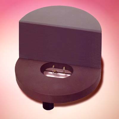 (b) - ST002: current range 3pA - 5nA |
|
With the Shear Force head the Solver-P47 is turned into a Scanning Near Field Optical Microscope. This head measure lateral forces (Shear Force) in resonance mode and offers the possibility to register an additional signal (for example optical (SNOM) or current): For measurements in gas or liquids, the device has a closed Gas-Liquid cell that can be used with any of the above Atomic Force Microscopy modes. With this cell the composition of the medium can be changed during the measurement. |
 SN002: Shear Force head | 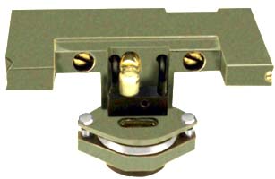 AU003: Hermetic gas-liquid cell |
|
A special variant of the Gas-Liquid cell supplies the possibility to work in an electrochemical environment in all AFM and STM modes. The Solver-P47 can be supplied with the stereo microscope video with CCD camera facilitating optical positioning. The resolution of the optical system depends on the CCD camera that is used and can be in limits of 1 - 2 microns. |
|